Thermally insulated cover templates
System components
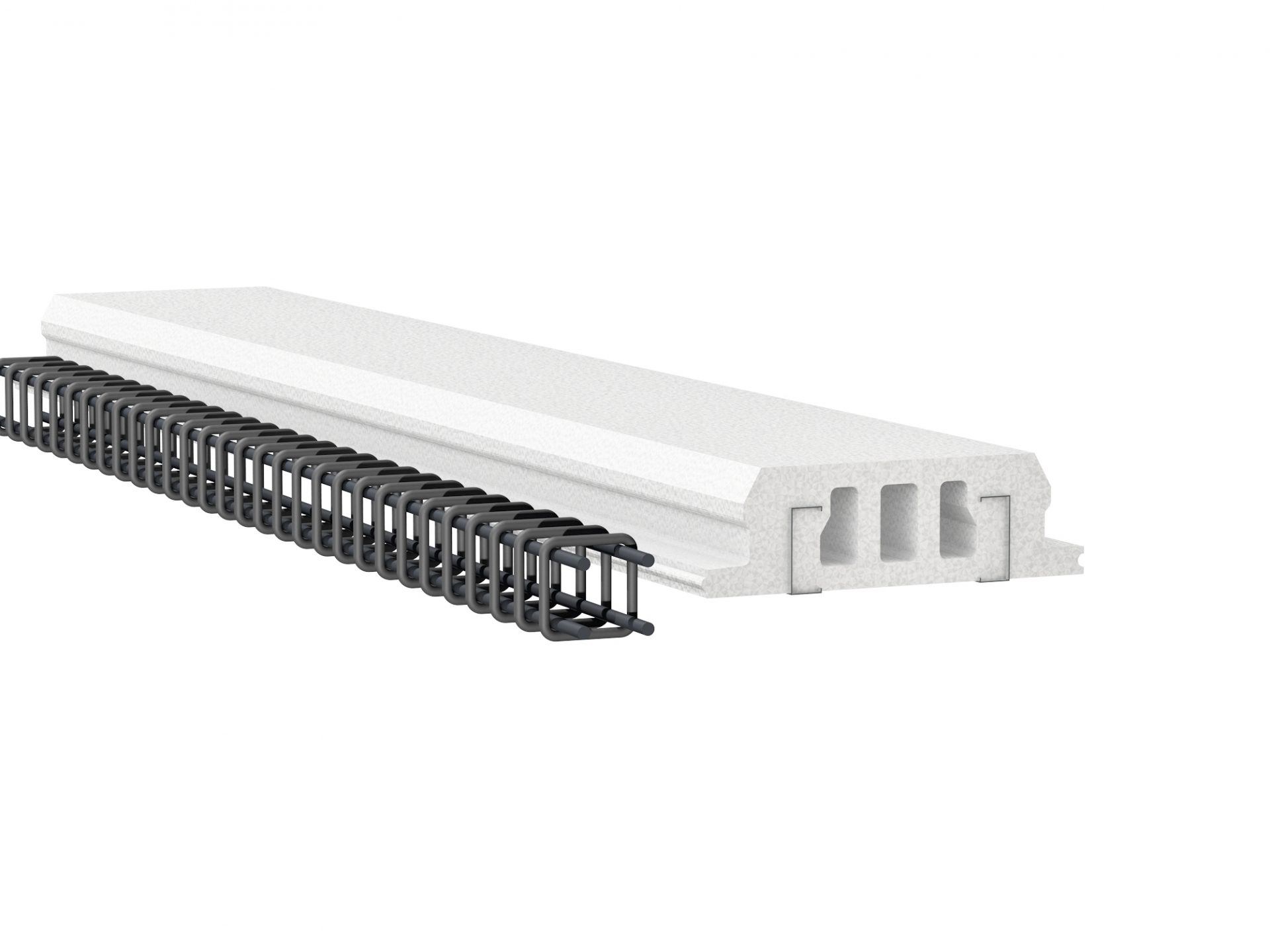
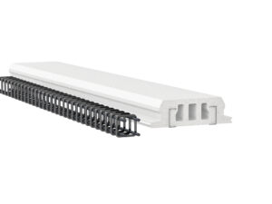
The permanent intermediate floor cover and roof templates are made of polystyrene foam EPS 100. The templates are 0.6 m wide (from 2 to 12 m); their height can be from 180 to 320 mm. There are 3 penetrated templates embedded (112 mm high). To increase the load-bearing capacities and affix finishing cover, polystyrene foam holds 2 U type metal profiles (120 mm high). The templates can be used both as intermediate floor cover templates and for roof layer concreting with a tilt up to 20o.
Site preparation
Before mounting a permanent intermediate floor cover and roof templates, one must prepare a temporary telescopic inventory supports and beams. The first supporting beam must be placed directly to the load-bearing wall. The supporting beam must be at least 100 mm wide. The supporting beam is to be mounted perpendicularly to the perforated steel galvanized profiles embedded in the cover elements. The maximum distance between temporary supports shall be 1.5 m. These supports must be made of wood or metal.
Form placement
Mounting polystyrene foam cover form is simple and can be completely done by one or two workers. The works must be started at the end wall. The cover template elements must be attached with a groove connection. To avoid concrete mass pouring in the element canals, the canal openings before mounting these elements must be closed (sealed) with special polystyrene foam plugs delivered with the cover template elements.
Installation of forms
If the elements are installed on walls built without Dobele panel system, the template shields should be placed around the perimeter. The shield height should be equal to the overall thickness of the cover – height of the cover template elements (180-320mm) + concrete cover height above the cover template elements (40-70mm). If there is no additional thermal insulation designed for the wall, a polystyrene foam thermal insulation layer shall be affixed to the shield. A bar tract should be mounted around the perimeter with 4 bars (with diameter of 10 mm). The bars are covered with covers (diameter of 5 or 6 mm) with 25-30 cm step. The minimum width of the concrete tract is 12 cm.
Steel mesh placement
When the forms are installed, the rail armature must be placed. Each rail creates an armature carcass made of four bars and cover. The two upper bars can be with 8 or 10 mm diameter, but the diameter of the lower bars can be calculated depending on the designed length, load, concrete mark and other factors. All bars must be covered with covers (diameter of 5 or 6 mm). The distance between covers is calculated as follows: ¼ of each rail edge is placed in a distance equal to the following: rail height divided by two; the remaining rail (middle) covers should be repeated with 25-30 cm step. There should be an armature grid placed on the whole plane (diameter of 5 or 6 mm); the grid openings should not exceed 200x200mm.
Opening placement
If the size of openings in the cover does not exceed 255, it should be placed in-between the profiles in the templates before any concreting works. If the opening is larger, there should be shield templates with additional bars all around it; the quantity and diameter thereof must be calculated. A communication outlet should be designed before concreting.
Concreting
After creating a template system and the required reinforcement and after placing the necessary shield templates, one must continue with cover concreting. Concreting works start from one corner and move across the whole plane. If the next floor will be built by the use of Dobeles Panel system, an outgoing armature must be embedded in unhardened concrete in sites where walls are to be placed. The concrete must be vibrated with a vibration machine or vibration device.